Hiển thị các bài đăng có nhãn SolidWorks Tips. Hiển thị tất cả bài đăng

Thứ Tư, 2 tháng 10, 2013

Layout Based Assembly Design


Do you evaluate your mechanism assemblies before investing 3D modelling time?

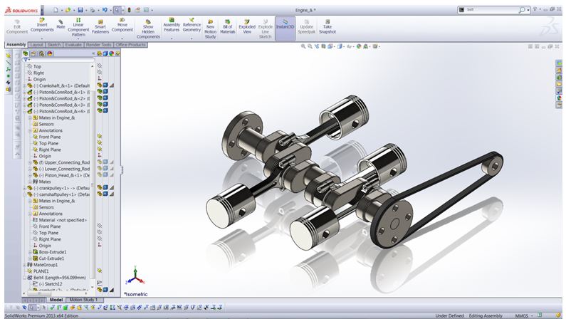
Having participated in several design projects requiring the development of a mechanism, I’m sure I’m not alone in investing a fair amount of time in a mechanism assembly which, according to my trusty pen and notepad will function beautifully, to find that the reality is that its fundamentally flawed.  So, how can SolidWorks help in this stage between notebook scribbles and a fully solid model?

Layout Based Assembly Design allows us to create & evaluate our mechanism assemblies as 2D sketches.  The car jack seen below for example has been created as a typical SolidWorks assembly, with several individual parts mated together to provide mechanism movement.


When fully retracting the jack, a fairly obvious design flaw with the top link becomes evident, meaning the jack doesn’t retract low enough. 

Of course, we could make some changes in this assembly to overcome this flaw, however given that I’ve already spent time creating the assembly and now, I’m  looking to spend more making changes, it may have been more efficient to conceptualise my mechanism as a Layout Based Assembly Design, then create the 3D geometry.


We begin our Layout Based Assembly Design using the ‘create layout’ button, once we’ve done so, we’re ready to sketch in our first component.
 
When using Layout Based Assembly Design, sketch blocks represent individual parts so we’ll turn our sketch entities into a single block using the ‘Make Block’ button.
To represent the rest of our components, we could either create them or if we already have them (as I do here) we can use the ‘Insert Block’ button.
 
Once we’ve inserted our subsequent blocks, sketch relations can be used to associate the blocks together.  In this case, I’ll be using a concentric sketch relation
 
Now with all my sketch blocks in place and sketch relations added, I can move the mechanism and begin to evaluate it.  The issue we identified from the original assembly now becomes evident.  The difference here is, as I’ve not had to create 3D geometry or even mate the components together I’ve identified this issue in a matter of minutes.
 
Rectifying the flaw is as easy as deleting the offending block and replacing it with a new one. Evaluation tools such as measure are supported in a Layout Based Assembly Design, so we can be sure we’ve improved the design.


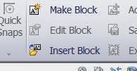
Once satisfied with our mechanism assembly we can convert the blocks to 3D geometry easily by right clicking on the block in the feature manager tree and selecting ‘Make Part from Block’
Notice at this stage the block is converted to a part file, which when right clicked has the option to either ‘open part’ or ‘edit in context’ from the toolbar at the top.
 
 
The end result of converting my sketch blocks to 3D geometry can be seen below.


Thứ Ba, 4 tháng 6, 2013

Could Top Down Assembly Modelling save you time?

Having recently joined the SolidWorks technical team at TMS CADCentre a lot of my time has been dedicated to expanding my SolidWorks knowledge by participating in SolidWorks training courses.  Although I had used SolidWorks extensively in my own design work and considered myself as somewhat of a seasoned user I was amazed at some of the functionality covered in the training courses that I simply was not aware of.
Top down modelling from Assembly Modelling is a prime example of this and will be the focus of this article.  By ‘Top Down’ we refer to creating parts in the context of the assembly as we go, opposed to the more commonly used ‘bottom up’ method wherein all the parts are created separately.
The intention with the crank shaft model seen below is to add a pulley.  The pulley and associated parts could be created separately and added (bottom up technique) but as I need to reference other parts in the assembly it makes sense to use the Top Down in context technique.

Before beginning you can set any subsequent parts created in the assembly to save as external part files under system options/assemblies.  If you do so, you will be prompted to define a save location upon new part creation.


To start adding your new part go to insert components and when prompted select a reference planer face.

The assembly is now ready for the creation of a new part.  As the geometry I require to create the pulley already exists I don’t need to bother re-creating it and can instead just do a simple convert entities command and a basic extrude.  The outer diameter is taken from the pulley at the opposite side of the crankshaft and the inner diameter defined by the pulley end shaft.


The new part appears in block colour for clarity until clicking the confirmation icon in the top right corner.  Note how the new part is now inserted into the tree and appears in the defined save location if you chose to ‘Save new components to external files’.


And that’s it! I’ve quickly and easily added a new part to my assembly without even having to create a sketch by using in context top down modelling.  Using the same quick process I’ll also add another pulley to simulate how this crankshaft could connect to the camshaft.
Notice I’m not constrained to referencing a face when creating my new part – I can use a plane, which is what I’ll do here.  The camshaft pulley is created using some simple geometry and a boss extrude.  Mating this pulley in place is not essential as it’s likely I would go on to construct the camshaft which the pulley would be fixed to.

Lastly, to complete my in context modelled pulleys I’ll use a belt to link them using the Belt/Chain tool.  Notice how the belt/chain tool inserts only a representative sketch line.

A top tip with the belt tool is to select ‘Create belt part’ under properties.  This creates the belt as a separate part, meaning it can then be opened and edited.  This is useful here as it means we can extrude it and have a better representation of a belt than a sketch line.

I hope you find this functionality as useful as I do when it comes to simplifying and quickening the process of adding parts to an assembly.  Now go try adding some in-context parts to that old assembly you have!

Thứ Năm, 6 tháng 12, 2012

Viewing different sheets at the same time

I’ve had a couple of customers asking me recently about the possibility of showing different sheets from the same drawings file at the same time on screen.

It is possible by following the following process.


Firstly open the document that has more than one sheet that you would like to view.


Go to Window – New Window – this will basically open a duplicate window


You can then use Window – Tile Horizontally/Vertically to see both of the windows.


Once you can see both of the windows, it is simply a case of selecting one of them and activating the alternate sheet.


As a small note, this will function in the same as having other linked files open. This means that if you make a change on one sheet, it will automatically translate that change in the other window.

A good example of this is shown in the image above. There are two windows of the same file open, each are showing different sheets. However by making the BOM sheet active in the second window, it also activates, (but doesn’t show) in the other window.

Thứ Năm, 6 tháng 9, 2012

Wonders of Weldments

3+ Way Mitres in Weldments
When building steel frames, particularly in circular tube you can strange results when 3 or more tubes come together and you and to trim them all back.  You could end up with something like this:

So how can I make it look like this? 


It's all in the trim order.  Edit the Structural Member feature and click on the joint so you get the Corner Treatment Dialogue box. 
What we are looking for is the Trim Order settings at the bottom.  For each of the groups simply set the Trim order to 1 and they will all mitre together.  It even works for 4 or more segments:

To see this in action you can check out our youtube page.

Creating a profile wrap for cutting
When working with tube in this way it can be tricky to work out how to cut the tube back to the correct finish so that it will fit first time.  What a number of people do is create a flattened version of the tube and print it out so that they can cut out the printed profile and wrap the paper around the tube so that it can be marked for cutting.
Here's how to do it.
First we need to save the bodies out. I could do this in the original part, but I'd prefer to keep these files separate.  You can either save each of the bodies out to individual parts, or you can do as I did here, right-click on the CutList folder and select insert into new part.  Then do a 1 degree cut in the tube:
Ensure that you only cut that one body.
Then use Insert bends from the sheet metal toolbar
Setting the K-Factor to 1 ensures that the outer face of the tube will not change in length when flattened.
Repeat for the other bodies and you are then ready to print the profiles. Simply create the flat patterns for each.  You could also use the export to .dxf to create quick simple profiles for the guys on the shop floor.

So there you have it a couple of tips for working with weldments.

Thứ Hai, 21 tháng 5, 2012

Mating Linear and Spherical Components

I was recently contacted by a customer who designs and manufactures a range of optical and crystal monitoring and control systems. Included in their design work is the requirement to position lens components with a high level of precision. This often includes using a spacer component to ensure that an energy source is a specified distance from the lens surface.

The customer wanted advice on how to accurately mate the spacer to the domed surface of the lens as automatic mates would not give him the result that he wanted. The following post has been written to assist users with similar issues.

The projection of a linear dimension onto a spherical surface produces an irrational number and you will therefore be unable to mate the surfaces directly together. However there is a way of working around this by creating sketches within the individual parts and mating these together instead as explained below.

For this example, a spherically domed lens is required to mate with a cylindrical tube spacer to be used within the prism assembly shown above. The transparency has been changed in the parts to make the images clearer.
If attempts are made to mate surfaces or edges together on the parts, the following results may be given.

If you attempt to mate the domed face and the related face on the spacer, the option of a Tangent mate is the only one available. This will position the face of the spacer on the tangent of the extent of the dome.


By selecting the domed face and the internal circular edge of the spacer, the required calculations to produce a coincident mate create irrational numbers and the geometry cannot be mated.


By selecting the circular face of the spacer part and the circular edge of the domed face of the lens part, the mate produced will pull the spacer part through the domed surface.


Solution for the problem


Open the Lens part and start a new sketch on a plane that dissects the domed face of the lens.

Select the silhouetted edge of the dome and use the convert entities function. This will create a 2D sketch profile of the dome. Ensure the sketch is left visible and save the part.


Open the Spacer component.  This example was constructed using a Boss-extrude followed by a cut extrude.
Open the sketch that defines the profile of the hole through the spacer. Use the sketch point tool and add a point that is coincident with the profile of the sketch that defines the hole.
Show the sketch that defines the profile of the hole so that it will be visible when you view the part in an assembly.


Now that the sketches in the part files have been created, they can be used to mate the parts together.


In an assembly that contains the lens and spacer parts, you can now mate the point that you created on the sketch for the profile of the hole in the spacer, with the silhouette sketch on the lens part.

 
This will ensure that the point will be coincident to the silhouette sketch


Make the temporary axes visible to be able to mate to the central axis of the lens. In this case the spacer’s axis will be mated to the axis of the lens.
The sketch point on the profile of the hole sketch is coincident with the silhouette edge of the domed surface of the lens, and will keep this relation when the parts axes are mated.
 
By mating the sketch geometry created together, the required result of the spacer connecting with the lens at their extents can be achieved


Thứ Năm, 12 tháng 4, 2012

New SolidWorks Support Resources

Some of you may have already noticed an addition to our Support page.  The SolidWorks Knowledge Base makes it easy for you to search for solutions to common issues though the Customer Portal.  Browse through the topics or enter a keyword in the search to be directed to the relevant section.

We have also added the Customer Forums section which gives you access to direct questions being asked by SolidWorks users.  Often these questions address a specific task within SolidWorks pertaining to a users job function.  Head over to our support page and see what questions are being asked right now.


The SolidWorks forums can be viewed by anyone but the Knowledge Base is only available to customers with a current subscription.