Hiển thị các bài đăng có nhãn SolidWorks. Hiển thị tất cả bài đăng

Thứ Tư, 2 tháng 10, 2013

Layout Based Assembly Design


Do you evaluate your mechanism assemblies before investing 3D modelling time?

Having participated in several design projects requiring the development of a mechanism, I’m sure I’m not alone in investing a fair amount of time in a mechanism assembly which, according to my trusty pen and notepad will function beautifully, to find that the reality is that its fundamentally flawed.  So, how can SolidWorks help in this stage between notebook scribbles and a fully solid model?

Layout Based Assembly Design allows us to create & evaluate our mechanism assemblies as 2D sketches.  The car jack seen below for example has been created as a typical SolidWorks assembly, with several individual parts mated together to provide mechanism movement.


When fully retracting the jack, a fairly obvious design flaw with the top link becomes evident, meaning the jack doesn’t retract low enough. 

Of course, we could make some changes in this assembly to overcome this flaw, however given that I’ve already spent time creating the assembly and now, I’m  looking to spend more making changes, it may have been more efficient to conceptualise my mechanism as a Layout Based Assembly Design, then create the 3D geometry.

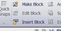
 
We begin our Layout Based Assembly Design using the ‘create layout’ button, once we’ve done so, we’re ready to sketch in our first component.
 
When using Layout Based Assembly Design, sketch blocks represent individual parts so we’ll turn our sketch entities into a single block using the ‘Make Block’ button.
To represent the rest of our components, we could either create them or if we already have them (as I do here) we can use the ‘Insert Block’ button.
 
Once we’ve inserted our subsequent blocks, sketch relations can be used to associate the blocks together.  In this case, I’ll be using a concentric sketch relation
 
Now with all my sketch blocks in place and sketch relations added, I can move the mechanism and begin to evaluate it.  The issue we identified from the original assembly now becomes evident.  The difference here is, as I’ve not had to create 3D geometry or even mate the components together I’ve identified this issue in a matter of minutes.
 
Rectifying the flaw is as easy as deleting the offending block and replacing it with a new one. Evaluation tools such as measure are supported in a Layout Based Assembly Design, so we can be sure we’ve improved the design.


Once satisfied with our mechanism assembly we can convert the blocks to 3D geometry easily by right clicking on the block in the feature manager tree and selecting ‘Make Part from Block’
Notice at this stage the block is converted to a part file, which when right clicked has the option to either ‘open part’ or ‘edit in context’ from the toolbar at the top.
 
 
The end result of converting my sketch blocks to 3D geometry can be seen below.


Thứ Ba, 4 tháng 6, 2013

Could Top Down Assembly Modelling save you time?

Having recently joined the SolidWorks technical team at TMS CADCentre a lot of my time has been dedicated to expanding my SolidWorks knowledge by participating in SolidWorks training courses.  Although I had used SolidWorks extensively in my own design work and considered myself as somewhat of a seasoned user I was amazed at some of the functionality covered in the training courses that I simply was not aware of.
Top down modelling from Assembly Modelling is a prime example of this and will be the focus of this article.  By ‘Top Down’ we refer to creating parts in the context of the assembly as we go, opposed to the more commonly used ‘bottom up’ method wherein all the parts are created separately.
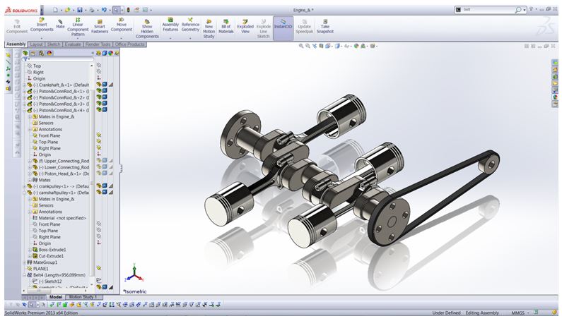
The intention with the crank shaft model seen below is to add a pulley.  The pulley and associated parts could be created separately and added (bottom up technique) but as I need to reference other parts in the assembly it makes sense to use the Top Down in context technique.

Before beginning you can set any subsequent parts created in the assembly to save as external part files under system options/assemblies.  If you do so, you will be prompted to define a save location upon new part creation.


To start adding your new part go to insert components and when prompted select a reference planer face.

The assembly is now ready for the creation of a new part.  As the geometry I require to create the pulley already exists I don’t need to bother re-creating it and can instead just do a simple convert entities command and a basic extrude.  The outer diameter is taken from the pulley at the opposite side of the crankshaft and the inner diameter defined by the pulley end shaft.


The new part appears in block colour for clarity until clicking the confirmation icon in the top right corner.  Note how the new part is now inserted into the tree and appears in the defined save location if you chose to ‘Save new components to external files’.


And that’s it! I’ve quickly and easily added a new part to my assembly without even having to create a sketch by using in context top down modelling.  Using the same quick process I’ll also add another pulley to simulate how this crankshaft could connect to the camshaft.
Notice I’m not constrained to referencing a face when creating my new part – I can use a plane, which is what I’ll do here.  The camshaft pulley is created using some simple geometry and a boss extrude.  Mating this pulley in place is not essential as it’s likely I would go on to construct the camshaft which the pulley would be fixed to.

Lastly, to complete my in context modelled pulleys I’ll use a belt to link them using the Belt/Chain tool.  Notice how the belt/chain tool inserts only a representative sketch line.

A top tip with the belt tool is to select ‘Create belt part’ under properties.  This creates the belt as a separate part, meaning it can then be opened and edited.  This is useful here as it means we can extrude it and have a better representation of a belt than a sketch line.

I hope you find this functionality as useful as I do when it comes to simplifying and quickening the process of adding parts to an assembly.  Now go try adding some in-context parts to that old assembly you have!

Thứ Hai, 3 tháng 6, 2013

3D CAD Sheetmetal using Excel in Geomagic Design

Geomagic Design 3D CAD (formerly Alibre Design) software from 3D Systems supports the use of Microsoft Excel files to drive design in all low-cost versions: Design Personal, Design Professional and Design Expert. Spreadsheet-driven parameters allow for company staff to specify design criteria without the use of any CAD software - only the final update need be applied using Geomagic. Microsoft Excel 2003, 2007 and 2010 are all supported in the software help documentation of Geomagic Design 2013. This article follows a simplified demonstration of setting up, linking to and executing Excel files for a sheet metal part.

To begin with, download Geomagic Design HERE (link). No special settings are required at this point during the installation. Note that Geomagic Design does not support integration with Open Office. By way of overview, our example team will generate example spreadsheets which we will use to update a 3D design, which will be saved and used to update a DXF file for CNC.
 
 
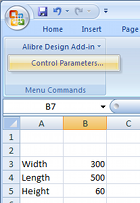
Every Geomagic Design installation includes an installation template which must be added to the Excel add-on list while running Excel once with administrator rights. Instructions as to how to do this with any supported version of Microsoft Office are available in the F1-help of Geomagic Design. Once properly installed, "Alibre Design Add-in" should be available from the Tools menu or Add-ins ribbon tab. Any numerical value cell may be selected to correspond to a Geomagic Design parameter, units specified and applied to a selected Geomagic Design file. For example we whip up something simple in Excel (shown right). Such a file can be created in Excel by anyone anywhere anytime (or it can be an imported CSV file etc)...

To update model parameters with the values listed in our spreadsheet, we need to start Geomagic Design and load the file in question. In our example we load the following basic Sheet Metal part, with overall parameters for "SM_length", "SM_width" and "SM_height":

 
Switching back over to our open spreadsheet, we select the Albre Design Add-in Control Parametrs (see above image of Excel). This opens a table in which cells are matched with parameter names:
 

To link spreadsheet values with model parameters, select an Active Session (model name currently open in Geomagic Design). All of the selected session's parameters will be listed by name. Now select the name of the desired model parameter from this list - and then the small "_" button down under Cell Reference and pick the workbook cell that you wish to link it to. Click the "Modify" button to finally change the parameter value to the one in the spreadsheet. Changes are shown immediately in Geomagic's active session model. Multiple changes can be made and applied at once by multi-selecting through the parameter list. If the spreadsheet is saved, the parameter links are saved with it.

To generate a DXF file of the final sheet metal design, a Geomagic drawing is used. Create a new Standard View. In the open Standard View Creation window, click the button "More Options". Check the option "Project as Flat Pattern" which will use the flattened version of the Sheet metal design for the projection view. Check that the projection scale is 1:1 and create the view. Once the flattened view is created, export the version of DXF which you require for CNC.

Geomagic Design is Australia's de facto low-cost 3D CAD alternative to SolidWorks and Autodesk Inventor. For more information about Geomagic Design or a free download, visit our website at http://www.caddit.net/cad-cam-software/geomagic.php

Thứ Sáu, 17 tháng 5, 2013

Geomagic Design 2013 Released on CADDIT Australia

CADDIT Australia has released the latest version of Geomagic Design 2013 (formerly called Alibre, now owned by 3D Systems). Geomagic Design 2013 is the most significant release since 2009, featuring hundreds of enhancements, improvements and fixes.

The base price of Geomagic Design remains at a modest $220. Geomagic Design is Australia's de facto choice for low-cost 3D parametric, mechanical design software which offers features similar to AutoCAD Inventor, SolidWorks and Solid Edge at a fraction of the cost. All versions of Geomagic Design includes advanced STL file export for 3D printing and rapid prototyping.

Geomagic Design Professional continues to offer photo-realistic rendering, STEP import/export and full 2D detail drawing. Geomagic Design Expert adds comprehensive sheet metal, direct (non-parametric) modeling, variant design and motion simulation capabilities. Geomagic Design Expert also offers reading of SolidWorks sldprt and sldasm files, Solid Edge and AutoCAD Inventor files. GeoMagic Exchange is a lower cost option available specific for CAD translation.

A full 30-day free trial of Geomagic Design can be downloaded from CADDIT Australia at this link:
http://www.caddit.net/cad-cam-software/geomagic.php

Chủ Nhật, 17 tháng 3, 2013

Alibre Design 2013 Preview - The Best Alibre Ever

The folks over at Alibre USA have been hard at work at what looks to be the best release ever of their flagship CAD software. Alibre is the defacto CAD software for low-cost parametric 3D mechanical part and assembly design in Australia. Priced modestly from A$220 for the base hobby user package to A$2200 for the top-end version including motion simulation, direct editing, variant design and direct reading of CATIA and Unigraphics files, Alibre is a more viable option than SolidWorks or Inventor for smaller budgets. Alibre 2013 will introduce literally hundreds of improvements in all areas of 3D modelling, assembly design, 2D drafting and section views, sheet metal design, bill of material and more. The overview document Alibre has provided to CADDIT Australia listing these enhancements is 59 pages long. Here are some highlights:

USER INTERACTION CONSISTENCY: In previous versions of Alibre, CRTL and SHIFT multiselect treated were differently in the various modes of Alibre. Alibre 2013 now uniformly implements multi-selection in the Design Explorer and Work Area, using Ctrl and Shift. More commands can also be applied to multiple objects in a single operation such as anchor, hide, suppress, align and scale view etc. Right-click behaviour has also been improved to ALWAYS show the options that are available to all selected items. (Previously there were cases where a right-click actually deselected all selected items.) "Apply" buttons have been added to numerous dialogue boxes so that changes can be seen before leaving many commands. Conflict visibility has been improved, dragging the "Dog Bone" has been fixed, real-time measurement data now appears in the status bar, some menu items have been consolidated, even the licensing dialogues have enjoyed some housekeeping. There is now a much more consistent user experience with the overall interface of Alibre. This is good new to those using Alibre for their everyday mechanical design work :)

UNDER THE HOOD: Alibre 2013 will be powered by Dassault's new ACIS V23 kernel, released six months ago (see announcement here). This means better modelling and problem-solving on the geometry level of Alibre. STEP file export includes multi-part assembly and drawing "packaging" (somewhat similar to progeCAD "eTransmit"), STL publishing for 3D printing enjoys better support for binary STL, and control of the STL data.

SKETCHING AND PART MODELLING: Sketching performance is significantly improved and more responsive, especially when zoomed in. Dimensions can now be placed between concentric arcs and circles to define the difference in their radii. All disjoint ends of a sketch (caused by DXF or DWG import, etc) are automatically healed when the active Sketch is exited. User is no longer prompted that sketch problems exist when only Disjoint Ends exist, as they are automatically healed. Pressing Escape while in 2D Sketch Mode now make the Select tool active. User can now import Points from a CSV file into a 2D Sketch as well as for 3D sketches. User can also designate any 2D dimension to be Driven during dimension placement or after dimension placement by modifying the dimension. Driven dimensions update in real-time as figures are moved or further define objects in the sketch. Driven dimensions can also designated to show up in the Equation Editor as a parameter. This effectively enables use dimensions from one part in another part. For part modelling itself, the THREAD tool has been improved with drop-down menus of thread definitions.

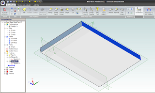
OTHER IMPROVEMENTS: In this blitz review of the upcoming release of Alibre 2013 we haven't even started to discuss what's new in Assembly design, drafting, sheet metal, BOM, third-party bonuses etc and this article would be WAY to long to include them all. There is one improvement we picked from sheet metal we wanted to mention here. There will be a brand new tool which allows designers to create sheetmetal bend lines directly from a sketch, complete with rips. These bend lines are used to fold a tab or flange. This is particularly useful if you are trying to recreate a sheet metal part from an imported 2D drawing of a flat pattern:

It is important to note that Alibre Design 2013 will not support Windows XP, except for general how-to questions unrelated to anything in the operating system. Users really need to be using Alibre 2013 on a computer running at least Windows Vista or newer. Users choosing to remain back with Alibre 2012 on Windows XP and on active subscription will continue to be supported. For further information about this upcoming release of Alibre 2013 in Australia contact CADDIT.net (link). A further announcement will be posted here when the software is availble for download and trial.

Thứ Tư, 18 tháng 4, 2012

Simulating The Repair Of Sports Injuries

We're all used to hearing about footballers and other professional athletes damaging their cruciate ligament or suffering some other tendon injury.  I remember being told once that they can repair this by cutting away more of the damaged tendon and it seemed like a crazy statement.  How can removing material make something stronger?
Time to do a little bit of medical Simulation!
I fired up SolidWorks and modelled a simple strip with two small tears on each side.  Keeping things symmetrical helped with the setup.  


Close up of the tear

A quick simulation was set up

And here's the results


Maximum stress here was just over 1GPa, almost double the yield limit of the material.
Clearly we are failing here so now for the repair!

All I did here was increase the angle of the cut from 10 to 170 degrees.  This removes 13% of the original bar.
So what did this do to the stress?  Let's take a look:

Wow!  The maximum stress has fallen by 800MPa, a 79% drop in peak stresses.  We can live to run another day!
But why does this happen?  How can removing material increase the strength of the part?
It's all to do with how the stress can spread through the part.  With the narrow/sharp tear the stresses can only act at the root because there are no stresses at the top of the tear openings, but by smoothing out the damage, stress can spread across the entire width of the part allowing more material to take up the strain.
Once again I was able to use SolidWorks Simulation to illustrate what seems to be a paradox, and get the truth.


Thứ Tư, 7 tháng 12, 2011

Solidworks output IGS

人家傳的車架檔

是一個叫做SLDPRT, SLDASM的檔

這不是Alias可以開的檔說= =

上網查了才知道這是Solidworks的專用檔


我不會Solidworks......所以一定要轉檔XD

轉IGS

至於轉法蠻簡單的~~~~~直接點另存新檔選IGS就好了~

Alias是分出一個Output選項


Solidworks
Photobucket

Save as IGS
Photobucket

open in Alias
Photobucket


reference
http://help.solidworks.com/2011/Chinese/SolidWorks/sldworks/LegacyHelp/Sldworks/ImpExp/HIDD_Export_Options_IGES.htm

Thứ Hai, 31 tháng 10, 2011

Alibre 2012 Now Released - Overview

Alibre 2012 was released recently on CADDIT Australia. Alibre is an affordable, easy-to-use 3D CAD software for mechanical design of parts, assemblies and design drawings. Files from SolidWorks, Solid Edge, Autodesk Inventor and other mechanical design software can also be used in Alibre. Alibre is best known for its low cost and simplicity: users can easily create complex 3D CAD designs for the fraction of the cost of other systems.

Alibre 2012 offers a completely reworked graphical user interface, with a style similar to other Windows 7 productivity applications. New tools have been added for surfacing, sketching, relations and more. .


Alibre Design introduced in-place editing last release, as an enhancement in 2D drafting. This year, in-place editing toolbars have been introduced for part modelling, notably for sketch creation. In-place editing greatly improves speed-of-interface by reducing mouse travel for each command, and need to manually change toolbars. Alibre Design 2012 also lets you project sketches to other sketches, letting you reuse the work you've already done in new features.

Two major enhancements have been included for surface modelling. Surfaces may now be pasted directly from either MoI (free with Alibre Design Expert) or Rhino CAD. A complete new toolset for surface manipulation includes commands for Split Surface, Trim Surface, Stitch, Convert Solid to Surface, Create Surface from Face, and Delete Face.

2D mechanical drafting enhancements include support for multiple leaders from a single annotation, more flexible hatching, improved drafting geometry constraints and border selection for notations. .

Other general improvements include the placement of InterDesign relations in Alibre Design's feature tree and secondary cuts for sheet metal parts. For a free 30 day trial of the new Alibre 2012 - either as Windows XP 32-bit or Windows 7 64-bit native application - download Alibre 2012 HERE.

CADDIT has been supporting Alibre Design products in Australia since 2008. For more information about Alibre Design in Australia, contact CADDIT.net HERE.

Thứ Năm, 24 tháng 3, 2011

SolidWorks Alternative in Australia

SolidWorks, Inventor and Solid Edge are just some examples of legacy 3D CAD solutions supported by Alibre Translate - a feature available with Alibre Design Expert at no additional cost. For those not familiar with Alibre, Alibre is an easy-to-use low cost parametric 3D CAD system mainly for mechanical engineering design of parts, assemblies, sheet metal and more. Alibre Translate (Now free with Alibre Design Expert) not only offers direct Solidworks file import of .sldprt and Solidworks .sldasm assemblies, but also Autodesk Inventor .ipt and .iam files, Solid Edge files and much more.
Alibre easily handles large SolidWorks assemblies like this laptop computer

SolidWorks users should have little trouble understanding Alibre's straight-forward solid modelling and assembly design interfaces. feature sketch, extrusion, subtraction, shelling, draft, lofting are all functions also supported in Alibre Design. Alibre Design Expert adds non-parametric (direct) editing techniques commonly found in systems costing several times more than Alibre Design Expert (less than AUD $1500 in Australia - see prices here). Expert also includes Keyshot photo-rendering and Moi 3D surfacing software at no additional cost.

Alibre also offers fully integrated CNC software for 2.5-axis, 3 4 and 5-axis milling machines. Alibre CAM basic comes free with Alibre Design Expert, offering as the name indicates basic 2.5-axis milling from within the Alibre interface. A full comparison of Alibre CAM options are shown HERE. Solidworks users can also import their SolidWorks model into Alibre CAM for manufacturing.

Alibre Design is an easy, inexpensive and intuitive option for SolidWorks users. Although Alibre 2D detailing and drafting environment is quite comprehensive, Alibre also integrates well with advanced 2D CAD drafting solutions like Autodesk AutoCAD or progeCAD, a low-cost AutoCAD clone. A free 30-day trial of Alibre Design can be requested directly from CADDIT Australia by following the links and downloading HERE.

Thứ Sáu, 30 tháng 4, 2010

3D Document Publishing from TransMagic

One of the sometimes overlooked (this author included) features of TransMagic 3D CAD translation software is its free 3D model viewer. TransMagic read and write a number of file formats using native libraries - CATIA, SolidWorks, JT, Siemens NX / Unigraphics, Autodesk Inventor, Pro/ENGINEER - as well as neutral formats like STEP, IGES & STL - the advantage being native, reliable 3D CAD translation between high-end CAD systems of very good quality. However what should be done to share a CAD file with a client or colleague who has no 3D CAD system at all?

Enter TransMagic's 3D web page publishing feature. This video briefly demonstrates using TransMagic to publish a STEP file to HTML and open with Windows Internet Explorer.

Saving a CAD model or assembly as an HTML page from TransMagic will create (at least) two linked files using the file name given - one HTML file which can be loaded from Windows Internet Explorer & an associated HOOPS ".hsf" file containing the actual 3D parts which use the HTML as a "container". Simply, zip or unzip both files together, upload send in email or save to the same hard disk (or server) location and open the HTML from Internet Explorer with the .HSF file present in the same directory. You can view this video's actual HTML page for yourself HERE.

Of course, HTML code can be edited to change colors, add a company logo or product information and web links as desired - so it is far more effective in making product presentations than a binary viewer - and transmits far more successfully in email. It also adds the possibility (perhaps also using TransMagic's batch-convert option) to publish 3D part catalogs on a website that visitors can navigate and "inspect" in real time 3D.

For Australia and New Zealand, TransMagic can be downloaded locally from CADDIT. From other lands, please refer to http://www.transmagic.com/.