Hiển thị các bài đăng có nhãn Revit 2012. Hiển thị tất cả bài đăng

Thứ Hai, 5 tháng 3, 2012

Rooms to 3D Mass – case-inc apps

image

A few weeks back, case-inc released their monthly app. The February 2012 instalment was a tool which allows you to convert a Room to a 3D Mass.

image

More details can be found on the case-inc website ….http://apps.case-inc.com/ The tool is really valuable, however, the initial release had some limitations. When you converted the Room, it was actually converting it to a Generic model. Not a big deal, but you needed to be aware of this. So after some positive critical feedback, our friends at case-inc made some tweaks! So now when you choose Rooms to 3D Mass, the output is indeed a 3D mass family! Now all they need to do is find a smart way for us to automatically name the generated families rather than a have a long winded database name; did I say I was demanding? ;-)

image

Well done guys & a big thanks you from the Revit community. :-)

Thứ Tư, 25 tháng 1, 2012

Rebuilding forms in Vasari or Revit 2012

This issue came up yesterday, a reasonable straight request…”I have built this surface in “PRODUCT”…….. (insert Rhino or AutoCAD). Can I rebuild it in Vasari or Revit as a water tight closed object, so I can do that I do that create floors by mass thingy?”

image

So here goes; this is what I was able to achieve. It should be noted that this may not work for all surfaces, but it certainly worked for this form. I started by creating a new mass family in Vasari / Revit. Next I imported the Rhino surface.

image

I then choose divide surface & picked the imported Rhino surface, you may need to tab select until you get to the surface, but you will be able to subdivide the surface.

image I then altered the UV grid parameters to something sensible, in this case 4 x 10.

image

The UV grid would act as a template to trace. Then, under Surface Representation I enabled Nodes.

image

Using model lines > spline through points, I was able snap to the nodes to generate a profile following the surface.

image

I repeated this a couple of times to build a series of closed profiles.

image

Next I deleted the imported surface. I half expected everything to disappear, but fortunately I the model lines remained! I then converted these lines to reference lines & closed the gap at the base with another reference line.

image

Then selected all the model lines & chose create form to build the form.

image

As I suggested, it should work for simple forms & is a relatively quick way to rebuild in Revit or Vasari….but don’t assume it will work for all. 

image

Thứ Hai, 23 tháng 1, 2012

Scan to BIM

image

This sneaked it way up onto labs at the end of last week. This is a preview technology for Revit 2012….be sure to check it out….

http://labs.autodesk.com/utilities/scan_to_bim/

“Point Cloud Feature Extraction for Autodesk® Revit® 2012 software is a free* technology preview that allows you to work with point cloud more easily in Revit. This plug-in automatically extracts useful geometry features from point cloud of buildings and creates basic Revit elements to aid the building modeling in Revit.”


Thứ Ba, 20 tháng 12, 2011

Very quick adaptive railings

Just a quick share on the possibilities of using a very simple adaptive family to create a railing family. The “point” to watch is the need to make the adaptive points vertical on placement. :-)

image

Thứ Sáu, 9 tháng 9, 2011

Creating custom fill patterns the easy way

So out of the box Revit comes with a useful set of hatch patterns which can be used in your projects to create drafting & model fill patterns. The hatch pattern file uses the same format as AutoCAD & ends with an file extension of .PAT. These hatch pattern file can be found in the following location……

C:\Program Files\Autodesk\Revit Architecture 2012\Data

imageYou can also create your own fill patterns directly in Revit, however you are limited to creating patterns which are either parallel lines or cross hatch.

imageWhat if you want to create custom fill patterns based on a material requirements or a specific design you have created? Well you are into writing the .PAT file, which is actually a simple plain text file. There is some great guidance on how to do this in Mastering Revit Architecture bible as well as the Revit help file.

Nether the less, architects are generally visual people, we draw & design; very few of us can write scripts & code! So this is where Hatch Kit Pro steps in. Its a $125 utility for creating hatch patterns & is well worth the money and it will save you hours of pain! Patterns can be created directly in the Hatch Kit Pro or imported as a DXF from say Revit or AutoCAD & then exported to generate the .PAT file. The following video steps through what I think is the quickest process for creating that pattern you have always wanted!

Thứ Sáu, 5 tháng 8, 2011

Revit 2012 – pebbles

Be sure to checkout Zach Kronz cool post of creating pebbles forms in either Revit or Vasari…..nice.

http://buildz.blogspot.com/2011/08/pebbles-bam-bam.html

image

Yep, that's right, this is Revit…..

Revit 2012 – dept of unfair – ellipses

Elliptical elements have always been rather awkward to create in Revit. For instance you can’t create an elliptical wall without first creating an elliptical mass & then performing the wall by face function.

image


Whilst you could easily argue that ellipses are the scourge of architectural design, cause they are a pain in the arse to set out. Nether the less they are an important form to any designer or interior designer. Anyway, I was having some fun the other day looking at the best way to divide an ellipse into a number of equal segments. My old school CAD head kicked in, draw the ellipse, draw a series of circles on the perimeter on the ellipse then draw lines from the centroid of the ellipse to intersect with the ellipse of the circle. So I started in a new Revit project, followed the above procedure only to find I could not snap a line to the intersection of the ellipse & the circle??? Hmmm this seemed a bit odd….a bug may be? Anyway, I jumped over to the conceptual massing environment ( CDE in project as well as a family), did the same exercise & everything worked peachy here!

I don’t know what the project environment has against ellipses, but it needs to get learn from its sibling conceptual mass environment & get with the kids! One for the development team me thinks.

Thứ Ba, 2 tháng 8, 2011

Revit 2012 – massing & voids

This may seem rather obvious to the seasoned Revit user; but for the new kids on the block, when using voids to cut massing geometry in Revit, sometimes you need to think a little differently. The process of using voids to cut geometry can be a bit confusing. This is especially so, since the way voids cut in the conceptual massing tools is a little different compared with voids in say the in-place editor or family editor.. For instance, take a look at the image below. This was created by generating a freeform surface using the massing tools….then roof by face to generate the actual geometry for the roof.…it looks reasonably straight forward to achieve, but you need more then two voids to cut the initial massing surface.

image

Let me explain in more detail….. image

So the surface was created using the massing tool, which consisted of a series of spline reference lines, then a surface generated between the reference lines. As indicated below.

image

Next up, a inner boundary & a outer boundary of reference lines where sketched. These will be used to form the voids which will cut the surface.

image

Now the natural logic here is to also create a large rectangle to go beyond the surface, like this…..

image

However, this is not going to work for us, because if you try & build the void, from the rectangle & trimming reference lines you are going to get the dreaded “Unable to create form element error”.

image

Instead, you need to create two voids from reference lines to cut away the excess surface. With a reference lines configuration like this.

image

The image below, hopefully explains it a little better.image

All we then need is to create a void from the inner reference lines to cut the opening & we are good to go.

image

You may need to use the Cut Geometry tool to force the cutting.

image

image

I hope the above makes sense, I guess I should really do a youtube video to explain it in more detail, but this should at least give you some useful guidance.

Thứ Ba, 12 tháng 7, 2011

Revit 2012 - Reporting Parameters in CW Panels

I must admit, I don’t why I hadn’t picked up on this one before, but at RTC USA there was an interesting discussion that took place as well as being highlighted by Harlan Brumms in his class on solving common Autodesk Revit Architecture problems on using reporting parameters in curtain wall panel families.
This got me thinking, if reporting parameters can indeed be used in curtain wall panel families, they should be able to drive the depth of panels. If you can report the width & height of a panel, this will provide you with an area value. This could then be used in conditional formula which will parametrically alter the overall depth of individual panels.
For this exercise I started with a curtain wall panel.rft
image
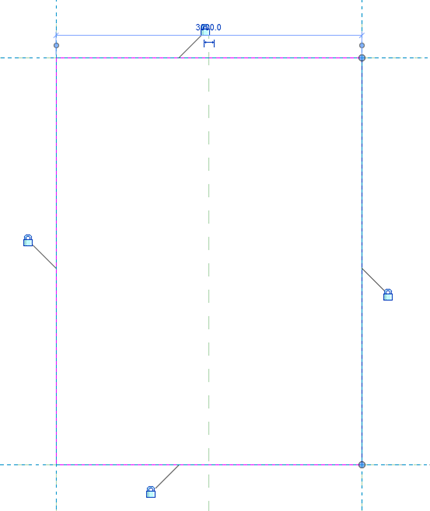
Next I drew a very simple extrusion in the front elevation plan & locked the extrusion sketch to the reference planes.
image
I then dimensioned the vertical & horizontal reference plans. Its important you dimensions the reference plans & not the level embedded in the family.
image
Then select the horizontal dimension you just created & pick the label feature to turn the dimension into a parameter. Name the parameter to something like “width”, set it to an instance parameter & ensure you check the Report Parameter radio button.
image
Repeat what you did for the width parameter, turning the vertical dimension into a reporting parameter labelled as “height”.
Go to the Ref. Level view, select the extrusion; in the Properties Palette, locate the Extrusion End parameter, hit the Associate Family Parameter button.
image
This will open up the Associate Family Parameter dialogue box. Hit the Add parameter button & create a new instance parameter called “depth”. This doesn’t need to be a reporting parameter.image
Go to the Family Types dialogue & create a new Area parameter as a instance.image
Go back to the Family Types dialogue box & do the following; in the formula for the Area parameter we will multiply the width X height to give us our Area.
image
Next we will add a conditional formula to the depth parameter. So we will use this formula as a test example.
if(area < 4 m², 1200 mm, if(area < 6 m², 600 mm, 100 mm))
What this conditional parameter will do formula is allow the depth of the panel to change based on the resulting area value of the panel. If is less the 4m squared it will be 1200mm thick, less the 6m & it will be 600mm, else it will be 100mm thick,
image
Next save your panel family with a suitable name. Start a new project, load your newly created panel family into the new project. Using the wall tool draw a straight segment of curtain wall. With the curtain wall selected, go to the Properties Palette, pick the Edit Type button, this will open up the Types Dialogue box for the Curtain Wall.
image
Set the Curtain Panel to your new loaded curtain wall panel. The cw system will automatically file with the new panel. Finally, using the Curtain Grid tool, start to divide up the curtain wall.
image
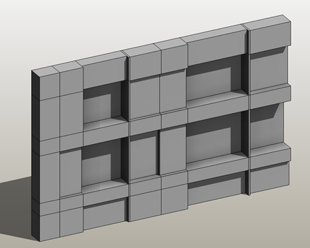
As you divide the curtain wall, depending on the panel size, the area of the panel will be calculated in turn informing the depth of the panels.
image
image
The values I added to the conditional formula are not cast in stone, you can easily modify them to get different results or even make a more complex  conditional formula. I have quickly knocked up a youTube Video which supports the above workflow, although I don’t follow it from start to finish, but it should reinforce what I did.

Thứ Sáu, 1 tháng 7, 2011

Lock profiles in Revit / Vasari conceptual massing

image

This came up a couple of times during RTC USA, but it seems that some people, whilst they are aware that the sketch profile feature got re-introduced in Revit 2011, they are not aware that you could lock the top & bottom sketches. This concept will only work with forms created from model lines; take a look at the attached youTube for more details. Sadly no audio, but you should get the general concept.